Leave a Message
We will call you back soon!
Your message must be between 20-3,000 characters!
Please check your E-mail!
More information facilitates better communication.
Submitted successfully!
We will call you back soon!
Leave a Message
We will call you back soon!
Your message must be between 20-3,000 characters!
Please check your E-mail!
Place of Origin: | BEIJING CHINA |
---|---|
Brand Name: | GFUVE |
Certification: | CE, UL, ISO9001, KEMA |
Model Number: | GF106T-1000A2500V |
Minimum Order Quantity: | 1 Set |
Price: | Negotiable |
Packaging Details: | Standard Export wooden box |
Delivery Time: | 1-2 Weeks |
Payment Terms: | Western Union, MoneyGram, T/T, , L/C, D/A, D/P |
Supply Ability: | 200Sets/Month |
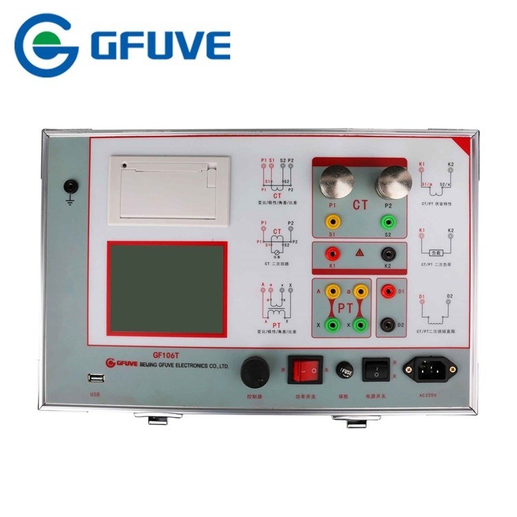
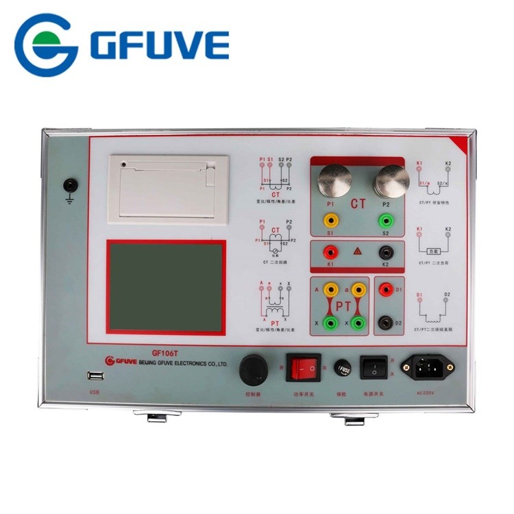
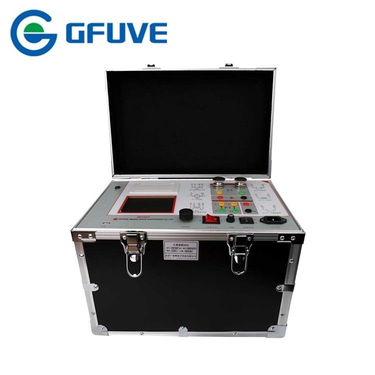
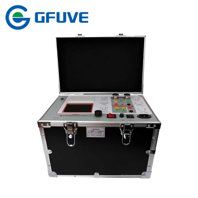
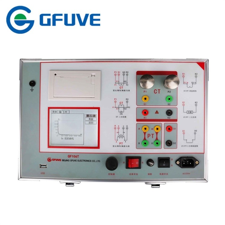
NAME: | CT ANALYZER | Accuracy: | 0.2%, 0.5% |
---|---|---|---|
Power Supply: | AC 220V±10% Or AC 110V±10%, 50/60Hz | Excitation Voltage Output: | 0-2500Vrms |
Excitation Current Output: | 0-5Arms (20A Peak-value) | Overall Dimension (L X W X H) (mm): | 400 X 250 X 250 |
Primary Current: | 0-1000a | Function: | Current Transformer Error Test |
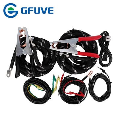
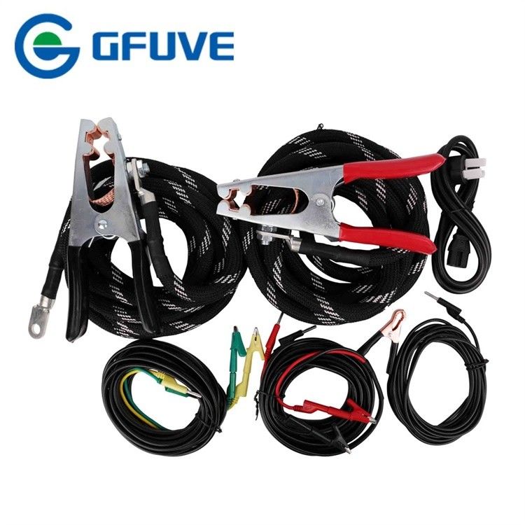
Cable Length: | 4m | Weight: | 20KG |
High Light: | circuit breaker analyzer,power transformer testing equipment |
The need for a comprehensive current transformer testing regime is evident when the alternative is considered: a catastrophically damaging current transformer fault. A fault leading to an open secondary could cause the primary current to overwhelm the insulation, causing the winding to short circuit. Megger’s range of current transformer test equipment allows you to construct an in depth test and maintenance programme to prevent problems before they occur.
A routine series of diagnostics and testing for your current transformer should include CT saturation testing to identify the knee point against IEEE or IEC standards, CT ratio tests to identify that the voltage ratio is within expected parameters and current transformer resistance testing for both the transformer windings and CT insulation resistance testing.
Saturation testing for a current transformer identifies the rated knee point against IEEE or IEC standards, the point at which the transformer is no longer able to output current in proportion to its specified ratio.
Ratio tests under normal load are achieved by comparing voltage applied to the secondary winding against the resulting voltage produced on the primary winding. Current transformer resistance tests inject test voltage to measure the DC current and calculate the resistance with allowance for temperature.
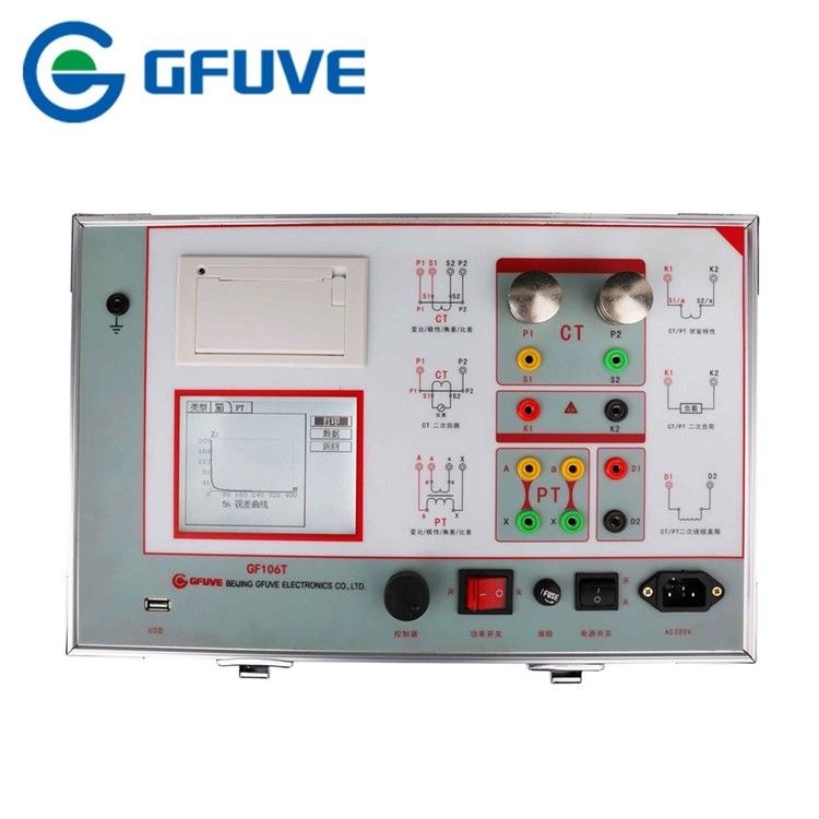
I. Current Transformer (CT) | II. Voltage Transformer (PT) |
---|---|
1. Magnetization curve | 1. Excitation characteristic test |
2. Transformation ratio test | 2. Transformation ratio test |
3. Polarity | 3. Polarity |
4. 5% and 10% error curve | 4. Withstand test of power frequency alternating current |
5. Current Injecting | 5. Degauss |
6. Degauss | 6. Calculation of knee point value |
7. Withstand test of power frequency alternating current | 7. Actual secondary load test |
8. Automatic calculation of excitation knee point value |
8. Resistance test |
9. Actual secondary load test | |
10. Resistance test |
Electrical parameters | ||
---|---|---|
Accuracy | 0.2%, 0.5% | |
Power supply | AC 220V±10% or AC 110V±10%, 50/60Hz | |
Excitation voltage output | 0-2500Vrms, | |
Excitation current output | 0-5Arms (20A peak-value) | |
Large current output | 0-1000A | |
Electrical parameters - continued | ||
Accuracy | ≤0.5% (0.2%RD+0.3%RG) | |
Secondary winding DC resistance measurement | Range | 0.1-300Ω |
Accuracy | ≤0.5% (0.2%RD+0.3%RG) | |
Secondary actual load measurement | Range | 5VA-1000VA |
Accuracy | ≤0.5% (0.2%RD+0.3%RG)±0.1VA | |
CT/PT phase error measurement | Accuracy | ±4min |
Resolution | 0.01min | |
CT ratio error measurement | Range | ≤25000A/5A(5000A/1A) |
Accuracy | ≤0.5% | |
PT ratio error measurement | Range | 1-500KV |
Accuracy | ≤0.5% | |
Standards | ||
Reference standards | GB1207-2006, GB1208-2006, GB16847-1997 IEC60044-1, IEC60044-6, IEC61869-2-2012 |
|
Safety standards | GB 4793.1-2007 | |
EMC | EMC standard 89/336/EEC | |
FCC Subpart B of Part 15 Class A | ||
IEC 1000-4-2 /3 /4 /6 | ||
Mechanical parameters | ||
Overall dimension (L x W x H) (mm) | 400 x 250 x 250 | |
Weight (kg) | ≤22 | |
Environmental conditions | ||
Relative humidity | 90RH% | |
Operating temperature | -10°C to +40°C | |
Altitude | ≤1000m |